
Digital Feature: First-stage ejector nozzle retrofit achieves meaningful performance improvement
J. R. LINES, Graham Corporation, Batavia, New York (U.S.)
Ejector systems are used in crude oil refining vacuum distillation. Predictable first-stage ejector performance is integral to a refiner meeting its throughput and yield objectives. Recent technological advances in ejector motive steam nozzle design can provide a low-cost/high value benefit for a refiner. A motive nozzle retrofit employing such advances may:
- Improve capacity
- Increase yield
- Reduce summertime instability
- Lower motive steam consumption
- Be optimized for one or more of the above.
In this current era of leveraging installed assets, this new technology can keep all the existing ejector system components and simply replace the motive steam nozzle within a first-stage ejector. Such a retrofit can be planned for a scheduled turnaround (TAR), or a short window pit stop between scheduled TARs.
Motive nozzle technological advancement. The new nozzle design centered on two key performance elements of an ejector. First is improving conversion of potential energy (motive steam supply pressure) to kinetic energy (velocity). The second pertained to improving entrainment efficiency. Both improvements permit better performance within an existing first-stage ejector diffuser. This technological improvement resulted from years of research and product development to optimize ejector performance.
There have been motive steam nozzle retrofits to overcome performance shortfalls due to excessive two-phase hydrocarbon loading in distillation column overhead load to an ejector system because of poor tower top mist elimination; however, this advancement takes it a step further. There is no tradeoff between suction capacity and maximum discharge pressure with this new type of nozzle.
The position of the nozzle within an existing diffuser is optimized based on priorities of a refiner. A first-stage ejector using standard nozzle technology responds in the following ways when the nozzle position is adjusted:
- Nozzle mouth pushed in toward the diffuser throat: The ejector’s suction pressure rises for the same overhead loading, while maximum discharge pressure increases
- Nozzle mouth pulled away from the diffuser throat: The ejector’s suction pressure lowers for the same overhead loading, while maximum discharge pressure decreases
There is commonly a tradeoff in performance when a standard motive steam nozzle retrofit alters the original supply nozzle position. New nozzle technology has no such tradeoff. When deployed, new nozzle technology improves performance without an adverse change in suction capacity or maximum discharge pressure.
For one recent example, FIG. 1 depicts a motive steam nozzle that was retrofit and pulled the nozzle mouth away from the diffuser throat, while not altering the suction capacity curve (top ejector) compared to the original supply (lower ejector). For this installation, motive steam consumption was lowered by 7.7%, maximum discharge pressure increased minimally by 1 mm Hg, and the new suction capacity curve tracked perfectly to the original suction capacity curve.
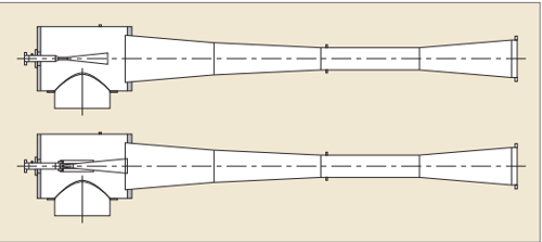
FIG. 1. Motive steam nozzle position comparison.
In this instance, the refiner was striving to improve summertime stability of the ejector system. During the hottest summer days, inlet cooling water temperature would rise above the design basis, resulting in the first intercondenser’s operating pressure to increase above the maximum discharge pressure of the first-stage ejector. This would cause an ejector system performance break, resulting in a considerable loss of yield, as the vacuum column’s overhead pressure would jump from a design of 15 mm Hg abs to 30 mm Hg abs–35 mm Hg abs.
FIG. 2 depicts the original suction capacity and maximum discharge pressure curves, and the curves using 7.7% less motive steam with a new nozzle retrofit. A motive nozzle with a 1.612-in. (40.9 mm) throat will use 7.7% less motive steam than the original supplied nozzle with a 1.678-in. (42.6 mm) throat.
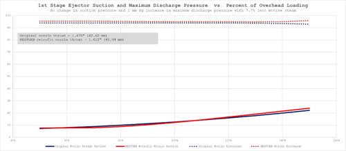
FIG. 2. Performance curve comparison.
Ejector maximum discharge pressure. The maximum discharge pressure of an ejector is the pressure below which performance is stable, shockwave is established and the ejector will track its suction capacity performance curve notwithstanding the backpressure (FIG. 3a). When the maximum discharge pressure (backpressure) of an ejector is exceeded, the shockwave collapses, performance is broken and the suction pressure jumps in the range of 30%–40% of the ejector’s discharge pressure (FIG. 3b). Performance is unstable, and the ejector will no longer track its suction capacity performance curve when this occurs.
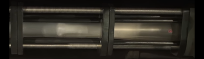
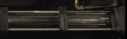
FIG. 3. A properly functioning ejector with shockwave (top), and a broken ejector performance with loss of shockwave (bottom).
Within the ejector manufacturing industry—following the Heat Exchange Institute’s guidelines—the maximum discharge pressure is the backpressure acting on the ejector, above which performance breaks and shockwave is lost, resulting in a definite change in suction pressure (performance).
Summertime instability. A recent survey of refiners concluded that summertime ejector system’s performance instability due to elevated inlet cooling water temperature is a top priority to address. Summertime performance breaks are a major problem, resulting in yield losses along with profit shortfalls. At times, a performance break may occur during the hottest hours of the day, while in the evening, ejector system performance might return to normal. At other times, a performance break can span the summer months.
This new motive nozzle technology can aid in ameliorating the adverse consequence of performance breaking due to warm inlet cooling water conditions. There are two avenues to explore with this new technology. One is to lower first-stage ejector motive steam consumption without affecting suction capacity or maximum discharge pressure of a first-stage ejector. By lowering the motive steam, consumption heat load to the first intercondenser is reduced. Following the classic heat exchange equation, Q = U * A * LMTD, if Q is reduced and the first intercondenser U and A are constant, then LMTD will be lower to balance the equation. The first intercondenser’s operating pressure (first-stage ejector discharge pressure) will be reduced, thereby lowering LMTD.
The second approach is to increase the maximum discharge pressure capability of the first-stage ejector without affecting the suction capacity curve or original motive steam consumption. The direction of movement by a first intercondenser when responding to increased cooling water inlet temperature is to increase its operating pressure. By increasing the first intercondenser’s operating pressure, the temperature at which steam begins to condense increases, thereby increasing LMTD in response to warmer inlet cooling water.
The path to follow can depend on the first intercondenser’s LMTD. When LMTD is tight—in the range of 10°F–15°F—then the better option is to increase LMTD by increasing the first-stage ejector’s maximum discharge pressure. When LMTD is high—such as 25°F or higher—then motive steam reduction or increased maximum discharge pressure are at parity. A general rule of thumb for typical first intercondenser operating pressures (65 mm Hg abs–95 mm Hg abs) is that each 2 mm Hg increase to maximum discharge pressure elevates steam initial condensing temperature 1°F. Put differently, a 2 mm Hg increase to maximum discharge pressure permits satisfactory ejector performance when cooling water inlet temperature rises 1°F above the design basis. For example, if an existing first intercondenser has a LMTD of 10°F, and with a retrofit using new nozzle technology, the maximum discharge pressure of the first-stage ejector can increase 4 mm Hg–5 mm Hg, allowing cooling water to rise 2°F above design basis without a performance break.
A recent analysis for three different first intercondenser LMTD conditions was undertaken to define if reduced motive steam or increased maximum discharge pressure would provide more benefit when addressing increased cooling water inlet temperature (TABLE 1). In each case, increased maximum discharge pressure offered the better option to address increased cooling water temperature. Again, the lower the LMTD of the first intercondenser, the greater the benefit is of increasing maximum discharge pressure rather than lowering motive steam usage.
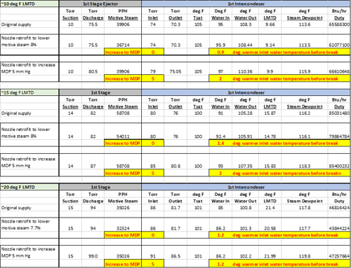
TABLE 1. Comparison of reduced motive steam or increased maximum discharge pressure to address warm inlet water conditions
Considering a recent case where inlet cooling water temperature exceeded the design basis, a standard nozzle retrofit to increase maximum discharge pressure by 5 mm Hg reduced frequency of an ejector system’s performance break by 30 d. This refiner had 46 d during summer when the inlet cooling water temperature exceeded the design basis of 85°F (FIG. 4). As a result of warmer inlet cooling water temperature, the first intercondenser’s operating pressure would rise above the maximum discharge pressure of the first-stage ejector, and performance would break (shockwave within the diffuser would be lost). Vacuum column pressure would jump approximately 20 mm Hg higher, and the yield loss for the refiner was significant. Using a 150,000-bpd refinery as the basis, a $15/bbl differential between vacuum gas oil and vacuum tower bottoms, and a 3% yield loss when the ejector system breaks, the economic improvement from 30 d of satisfactory performance is $2 MM. A low-cost nozzle retrofit can provide a high value add for a refiner.
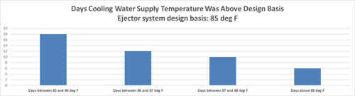
FIG. 4. Cooling water supply temperature trend.
Several years following the retrofit to increase maximum discharge pressure of the first-stage ejector, the refiner advised, “operations management is thrilled with the revamp, as there has not been a performance break.” It must be noted that this refiner also installed a trough distributor in the tower top to address liquid entrainment in the overhead load to the ejector system. A performance survey concluded satisfactory ejector system performance with inlet cooling water at 89°F and noncondensible gas loading at 65% of design. Prior to the revamp/nozzle retrofit, the ejector system performance would break at such warm inlet cooling water temperature.
Takeaways. The refining industry is challenged by summertime ejector system instability and lost yield. The primary cause for this is elevated inlet cooling water temperature. High inlet cooling water temperature can occur due to increased wet bulb temperatures, more heat load to the cooling tower system than originally designed and variations in cooling tower performance between start-of-run and end-of-run. With extended durations between TARs—typically 5 yrs–6 yrs—cooling tower performance can be challenged during the end-of-run the last couple years. With the long intervals between TARs, equipment fouling can play a role, as well.
A low-cost first-stage ejector nozzle retrofit with new technology nozzles can help address this common industry problem. The retrofit may not necessarily alter the first-stage ejector’s suction capacity curve, but can either lower motive steam usage to reduce the first intercondenser’s heat rejection or increase the first-stage ejector’s maximum discharge pressure to permit satisfactory performance when the first intercondenser’s operating pressure rises due to warm inlet cooling water temperature.


Comments